Wien bridge
The Wien bridge is a type of bridge circuit that was developed by Max Wien in 1891.[1] The bridge comprises four resistors and two capacitors.
Bridge circuits were a common way of measuring component values by comparing them to known values. Often an unknown component would be put in one arm of a bridge, and then the bridge would be nulled by adjusting the other arms or changing the frequency of the voltage source. See, for example, the Wheatstone bridge.
The Wien bridge is one of many common bridges.[2] Wien's bridge is used for precison measurement of capacitance in terms of resistance and frequency.[3] It was also used to measure audio frequencies.
The Wien bridge does not require equal values of R or C. At some frequency, the reactance of the series Rc–Cc arm will be an exact multiple of the shunt Rd–Cd arm. If the two Ra and Rb arms are adjusted to the same ratio, then the bridge is balanced.
The bridge is balanced when:[4]
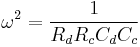 and
and 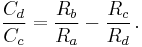
The equations simplify if one chooses Rc = Rd and Cc = Cd; the result is Rb = 2 Ra.
In practice, the values of R and C will never be exactly equal, but the equations above show that for fixed values in the c and d arms, the bridge will balance at some ω and some ratio of Rb/Ra.
See also
References
- ^ Wien 1891
- ^ Terman 1943, p. 904
- ^ Terman 1943, p. 904 citing Ferguson & Bartlett 1928
- ^ Terman 1943, p. 905
- Ferguson, J. G.; Bartlett, B. W. (July 1928), "The Measurement of Capacitance in Terms of Resistance and Frequency", Bell System Technical Journal 7 (3): 420–437, http://www.alcatel-lucent.com/bstj/vol07-1928/articles/bstj7-3-420.pdf
- Terman, Frederick (1943), Radio Engineers' Handbook, McGraw-Hill
- Wien, M. (1891), "Messung der Inductionsconstanten mit dem "optischen Telephon" (Measurement of Inductive Constants with the "Optical Telephone")" (in German), Annalen der Physik und Chemie 280 (12): 689–712, doi:10.1002/andp.18912801208